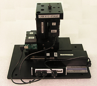
Introducing the Mini Hexapod Platform

The Mini Hexapod Platform (MHP) system is a relatively low cost kinematics platform that allows motion with six-degrees of freedom. These motions are in the X, Y, and Z direction, with rotations about those axes. Six linear actuators are placed in a triangular pattern to achieve a rigid, stable, and precise movement while carrying a load. With its dedicated drive electronics and Windows user interface, the control of the platform’s motions is simplified for ease of use.
If your application requires slow precise point to point motions with 0.001 millimeter repeatability, then you do not need the more expensive platforms on the market. The Mini Hexapod Platform system may be the answer you have been looking for.

System Basics
The Mini Hexapod Platform (also known as a Stewart Platform) system consists of a six actuator (Hex) movable Platform, an actuator Controller, Power supply, Cables, and a Windows based (user supplied) PC with a USB port. The actuators are commanded to move the platform by the User with the PC through its USB port. The User’s Cartesian coordinate move commands are transformed into commands for moving each of the six actuators using the Actuator Controller. Status and positional information of each of the actuators is also provided to the PC from the controller.
Customization
Picard Industries specializes in custom application and design of the MHP system. Many different sizes of linear actuators are available to fit your requirements.
Contact us with your requirements and we’ll be happy to help.
Mini Hexapod Platform Software
- Six-Dimensional (6D) motion control.
- X, Y, Z, with rotations Rx, Ry, Rz.
- Simple Cartesian coordinate entry.
- Definable Positions with memory.
- Re-Definable coordinate references.
- English or Metric units.
- PC Windows based, allows multiple MHP systems to run concurrently.

Manage Coordinate Systems
The left side of this dialog shows all of the coordinate systems in a tree view, with each coordinate system listed under its reference. Click on the triangle to the left of a coordinate system to expand or collapse the coordinate systems for which it is the reference. The right side of the dialog shows the definition of the currently selected coordinate system. Click on a coordinate system in the tree view (left side) to show its definition in the right side. The definition contains a pull-down for the reference coordinate system and edit boxes for the 6 numbers used to define the transformation for this coordinate system. This transformation describes the location and orientation of the current coordinate system in relation to its reference coordinate system.

Manage Positions
The left side of this dialog shows all of the defined positions in a list. Each listed position is stored with reference to a coordinate system. Select a position by clicking on its name. The right side of the dialog shows the values that define the position and its selected reference coordinate system. New positions can be defined or edited with the click buttons in the upper left of the dialog. Descriptions of defined position and its use can be stored in a text box in the lower right of the dialog.


